One long or two short membranes
The standard 400C has one 2.5 × 40-inch membrane. Compact has two 2.5 × 20-inch elements. Inspect the installed pressure vessels after any retrofit.

SPECTRA OWNER GUIDE
Find the two seawater prefilters, carbon flush filter, standard or Compact membrane, Connect controls and 10% Clark Pump parts. Follow the original Newport 400C drawings and inspect the installed hardware before ordering.
12V / 24V / 48V DC · Standard / Compact · Connect controlsRead the system label, voltage and number of membrane vessels.
MATCH THE INSTALLED SYSTEM
The standard 400C has one 2.5 × 40-inch membrane. Compact has two 2.5 × 20-inch elements. Inspect the installed pressure vessels after any retrofit.
Match the system label and installed electrical module. The 12V configuration has a 24V step-up power supply; the 48V diagram identifies a 48V-to-24V supply. Neither makes an 8–24V booster pump a direct 48V part.
The 400C is the Connect-control generation. Its remote display, local display option, sensors and control board are distinct from older MPC upgrades.
SEAWATER AND FRESHWATER FILTERS
The 20-micron and 5-micron seawater cartridges are both nominally 10 inches long × 2.5 inches in diameter. Seawater passes through the 20-micron stage first, then the 5-micron stage. The carbon cartridge filters the separate freshwater-flush supply and is not interchangeable by function.
| Stage | Cartridge | Housing & seal |
|---|---|---|
| Seawater, first stage | FT-FTC-20 · 20 micron Nominal 10 × 2.5 in | Three-piece housing Housing O-ring |
| Seawater, second stage | FT-FTC-5 · 5 micron Nominal 10 × 2.5 in | Three-piece low-pressure housing Matching wrench |
| Freshwater flush | FT-FTC-CC · carbon Nominal 10 × 2.5 in | Three-piece housing or modified Z-Ion bowl. Check installed hardware. |
Before the pumps, a six-inch sea strainer catches larger debris. The standard screen and seal do not automatically fit the newer plastic strainer. The manufacturer drawing separately labels its plastic screen FT-STN-6SP.
Seawater filters ↗ · Strainer and flush module ↗ · Manufacturer filter dimensions ↗
FOLLOW THE WATER
Use the actual Spectra drawings to identify modules. The 3D model below illustrates the Clark Pump internals; no 3D CAD is claimed for the rest of this Newport system.
Seawater enters through a dedicated thru-hull. The six-inch strainer and booster pump sit ahead of the feed module; the plumbing diagram calls out placement below the waterline.

The pump head and motor move feed water through the 20-micron and then 5-micron filters. The 12V and 48V systems include different conversion hardware; match installed motor and supply rather than assuming boat voltage is motor voltage.
mag-drive vane pump head · 20-micron element · 5-micron element
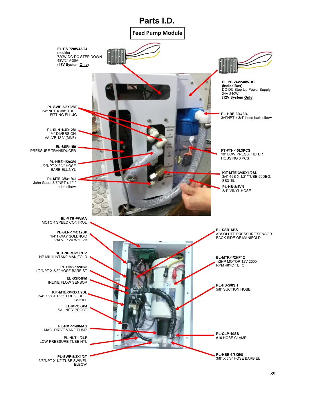
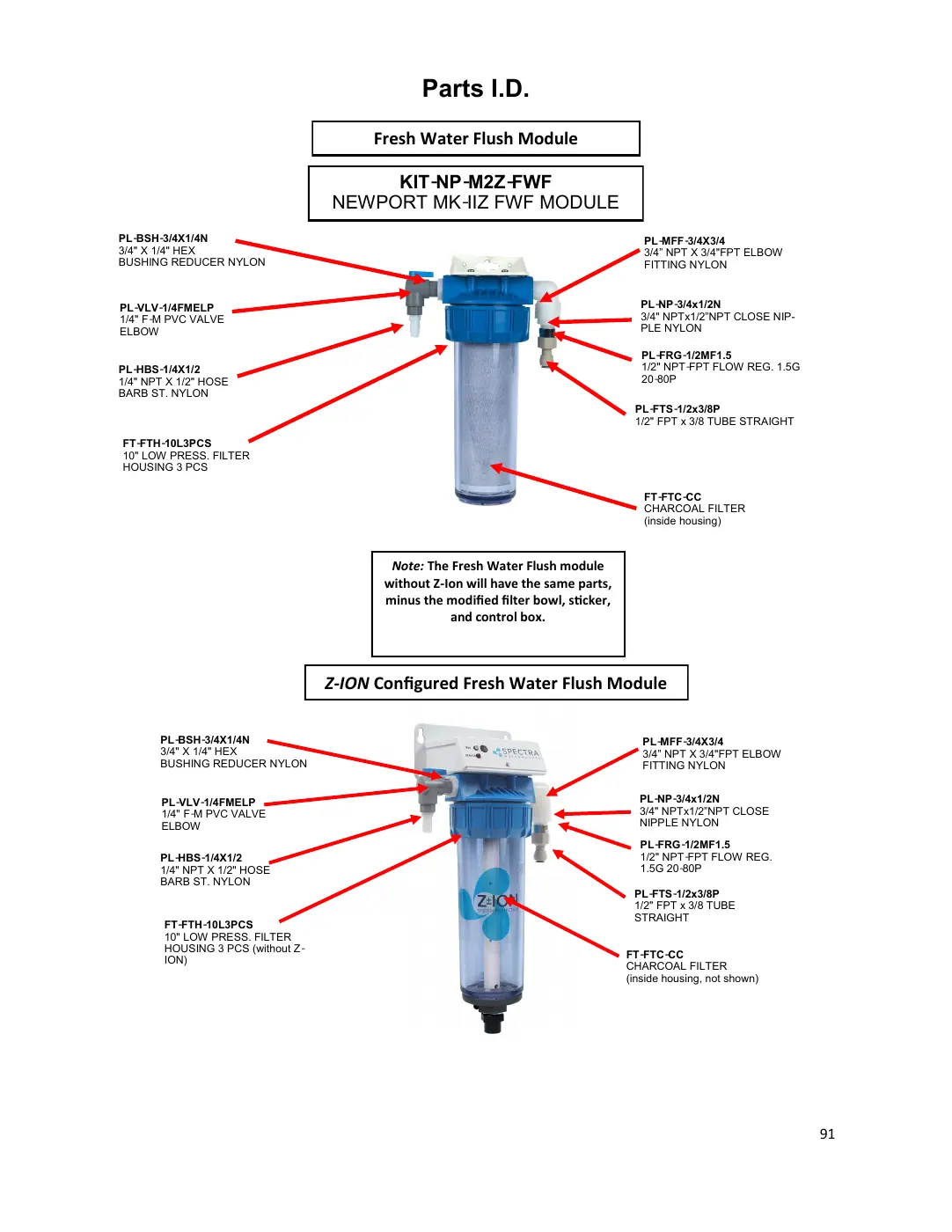
Freshwater passes through a carbon cartridge before reaching the system. An optional Z-Ion bowl changes the flush module; Connect sensors and diversion hardware are in the manifold and control box. Match the installed generation.
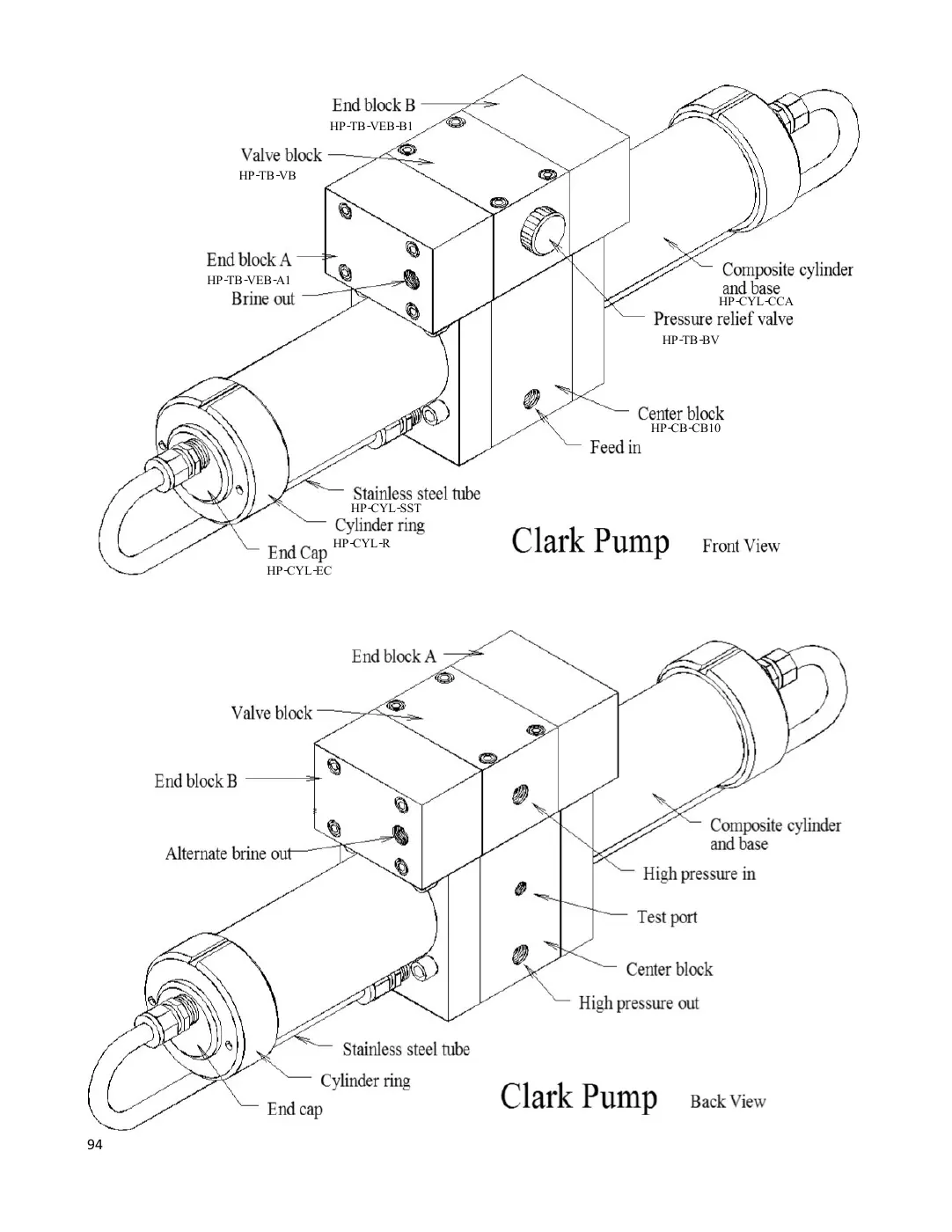
The Clark Pump recovers pressure energy. The standard system uses a long membrane vessel, while Compact uses two short vessels. The Newport exploded drawing labels HP-CB-CB10, a 10% center block.
standard membrane · Compact membrane · Explore the pump internals
INSIDE YOUR CLARK PUMP
Start with the outside, then open the reversing valve, center block or cylinder assembly to identify the parts inside.
Illustrated 10% Clark Pump arrangement. Reconstructed shapes, threads and separation distances are approximate. Match the installed pump ratio and revision before ordering; use Spectra’s Newport manual for disassembly.
Explore the external parts.
Select “Load 3D” to rotate and separate the pump. The component selectors work without loading the model.
Reset reassembles this section and restores the full view.
Choose a component to see its part reference.
These component references cover all four views. Open a component in 3D to locate it, then review its product requirements before ordering. Counts in the illustration are not package or order quantities.
Center block for the installed 10% Clark Pump, sold without inserts. The center-block bore must match the larger 10% piston rod and SO-HPP-PR10 seals. Check pump ratio and revision after any replacement.
View part & current priceSource drawing ↗Contains the annular rings and reversing spool. The pressure-relief valve screws into this block.
View part & current priceSource drawing ↗One of the two reversing-valve end blocks. A and B are distinct; compare the actual brine-discharge and reset-button arrangement.
View part & current priceSource drawing ↗End block B has an identifying indentation shown in the rebuild manual. It is not interchangeable by appearance alone with end block A.
View part & current priceSource drawing ↗Two identical cylinder-and-base assemblies attach to the center block in the documented pump.
View part & current priceSource drawing ↗Closes the outer end of a cylinder. Its seal and retaining ring are separately identified in the drawing.
View part & current priceSource drawing ↗The threaded ring retains the cylinder end cap. Thread geometry is simplified in this illustration.
View part & current priceSource drawing ↗The formed tube connects the cylinder-base fitting to the end-cap fitting. Match the installed arrangement and fitting revision.
View part & current priceSource drawing ↗Located on the reversing valve block. The SO-HPP-RV O-ring is a separate service item.
View part & current priceSource drawing ↗Seals the relief valve where it fits into the valve block.
View part & current priceSource drawing ↗Two annular rings sit inside the valve block around the reversing spool. The four annular-ring O-rings are separate items.
View part & current priceSource drawing ↗The rebuild guide shows four seals for the pair of annular rings.
View part & current priceSource drawing ↗The Newport drawing labels this assembly KIT-HP-10VSA; the 2024 rebuild sheet uses KIT-HP-VS10 for 7%/10%. These reference labels are not treated as a verified replacement chain or mapped to a bare spool listing.
Reference only; no verified purchase link.Source drawing ↗Two spool pistons fit inside the end blocks. The 20% piston and seal are different; they are excluded here.
View part & current priceSource drawing ↗O-ring in each end-block bore for the 7%/10% spool piston. Check the pump ratio before ordering.
View part & current priceSource drawing ↗A spacer ring is shown between the valve block and each end-block piston.
Reference only; no verified purchase link.Source drawing ↗Large O-ring at each valve-block end face, separate from the spool-piston seal.
View part & current priceSource drawing ↗Seals the larger valve port at the block interface. The manual also calls this a brine-port seal.
View part & current priceSource drawing ↗Small O-rings seal the pilot passages at the block interface.
View part & current priceSource drawing ↗The 10% Clark Pump uses one 7/8-inch piston rod. Pair this replacement with the installed 10% center block and its correct rod seals.
View part & current priceSource drawing ↗Two SO-HPP-PR10 seal locations are shown in the 10% center block. Match the larger 10% rod, and check the product’s supplied quantity before ordering for both locations.
View part & current priceSource drawing ↗Internal pilot spool in the center block, separate from the larger reversing spool in the top valve block.
View part & current priceSource drawing ↗Four O-rings are shown for the pilot spool, inside the center block.
View part & current priceSource drawing ↗Pin associated with the pilot-spool mechanism. Pin seals and clip rings are separate service items.
View part & current priceSource drawing ↗Seal carrier at the pilot pin. The SO-HPP-PS pin O-ring is identified separately.
View part & current priceSource drawing ↗O-ring for the pilot-pin sealing assembly.
View part & current priceSource drawing ↗Retaining clip for the pilot-pin assembly. The split-ring form is simplified.
View part & current priceSource drawing ↗Complete check-valve assembly reference from the rebuild material. The Newport drawing identifies the individual seat, poppet, spring and retainer; no complete-kit shopping match is asserted here.
Reference only; no verified purchase link.Source drawing ↗Seat used with the check-valve sealing O-ring. Four check valves are shown in the center block.
View part & current priceSource drawing ↗O-ring fitted to the check-valve seat.
View part & current priceSource drawing ↗Moving valve inside its retainer. The drawing separates it from the complete KIT-HP-CVK assembly.
View part & current priceSource drawing ↗Retainer surrounding the poppet and spring. The rebuild manual distinguishes inlet-side notched retainers; verify the actual revision.
View part & current priceSource drawing ↗Spring within the check valve. Its coil pitch and wire size here are illustrative.
View part & current priceSource drawing ↗Small washer in the check-valve assembly, identified on the rebuild sheet.
View part & current priceSource drawing ↗Separate sealing O-ring around a check-valve port at the cylinder interface.
View part & current priceSource drawing ↗The same source part number is shown for cylinder-to-center-block sealing and the cylinder end-cap O-ring. Order for the repair locations you are servicing.
View part & current priceSource drawing ↗The rebuild guide identifies a one-piece nylon piston for 7% and 10% pumps. The separate 20% piston seal and bushings are not shown here.
View part & current priceSource drawing ↗The Newport cylinder drawing labels PL-MTS-3/8X1/2B; newer high-pressure module drawings use stainless fittings. Match the installed fitting material and revision. This illustrative fitting has no direct purchase link.
Reference only; no verified purchase link.Source drawing ↗The drawing identifies four longer bolts joining the valve block to the center block. Dimensions are omitted because the source annotation and SKU differ.
Reference only; no verified purchase link.Source drawing ↗The rebuild sheet shows eight shorter bolts for the end blocks. The illustration does not specify installation torque.
Reference only; no verified purchase link.Source drawing ↗Sources: Newport manual, pages 94–97; Clark Pump rebuild manual, May 2024. The Newport exploded drawing identifies the 10% center block. Match the installed pump ratio and revision before choosing its center block, rod or seals. The reconstruction remains subject to technician geometry review.
10% distributor rebuild kit and 7% / 10% seal-and-O-ring kit cover different scopes. Review contents before buying individual parts as well. Repair-and-return service and Advance-exchange service have return arrangements; they are not ordinary boxed rebuild kits.
OPTIONS & REPLACEMENT CHOICES
Standard: one 2.5 × 40-inch membrane kit replaces the single original element. The end-plug repair kit and retaining ring are separate vessel hardware in the standard drawing.
Compact: two short 2.5 × 20-inch kits replace both original elements; each product is one kit. Spectra also calls the short SKU 21 inches in catalog naming. Check the installed short-vessel drawing before selecting any end-plug or ring hardware.
Standard membrane ↗ · Compact membranes ↗ · Standard vessel hardware ↗
Remote display and cable differs from display only and the optional local display. The salinity probe measures product water; it does not replace the control box.
These are Connect controls. MPC-3000 to MPC-5000 conversion kits address a different generation.
The standard six-inch screen and seal should match the installed body. Plastic strainer kit is a different assembly.
Optional Z-Ion replaces the regular carbon-filter bowl with a modified arrangement. The 48V application needs Spectra confirmation in the current catalog mapping.
MATCH THE REVISION
These product pages remain available for identification. The current drawings do not establish a universal exact replacement for every revision and voltage. Give Spectra the system label, the component label and a photo of its connections.
Earlier ECI manifold is listed alongside an updated Z-Ion/Intake drawing. Compare the installed manifold, valves and connectors. Ask Spectra which complete assembly matches its revision.
NP-400C-12 · NP-400C-12S · NP-400C-24 · NP-400C-24S · NP-400C-48 · NP-400C-48S
Inspect product listingZ-Ion intake manifold option. Ask Spectra whether the complete Z-Ion assembly matches the installed manifold generation and whether the original valves transfer.
NP-400C-12 · NP-400C-12S · NP-400C-24 · NP-400C-24S · NP-400C-48 · NP-400C-48S
Inspect product listingAnother ECI/Z-Ion intake assembly appears in the catalog. The current drawing labels SUB-NP-MK2-INTZ. Ask Spectra to identify your installed manifold revision before ordering.
NP-400C-12 · NP-400C-12S · NP-400C-24 · NP-400C-24S · NP-400C-48 · NP-400C-48S
Inspect product listingThe drawing labels a sea-strainer/booster module, while the catalog title references NP700/1000. Confirm package contents and Newport 400C application with Spectra.
NP-400C-12 · NP-400C-12S · NP-400C-24 · NP-400C-24S · NP-400C-48 · NP-400C-48S
Inspect product listingThe generic feed-module drawing labels a 12V motor, while the model has 12V, 24V and 48V system options and conversion hardware. Confirm the installed motor label, PWM assembly and supply path with Spectra.
NP-400C-12 · NP-400C-12S · NP-400C-24 · NP-400C-24S · NP-400C-48 · NP-400C-48S
Inspect product listingThe PWM assembly may depend on the controller and motor revision. Confirm the installed board and wiring with Spectra before replacement.
NP-400C-12 · NP-400C-12S · NP-400C-24 · NP-400C-24S · NP-400C-48 · NP-400C-48S
Inspect product listingRepair-and-return 10% pump service has core and shipping terms. Confirm the installed ratio, eligibility and service process with Spectra.
NP-400C-12 · NP-400C-12S · NP-400C-24 · NP-400C-24S · NP-400C-48 · NP-400C-48S
Inspect product listingRemanufactured 10% exchange is subject to core and revision requirements. Confirm the installed pump and terms with Spectra.
NP-400C-12 · NP-400C-12S · NP-400C-24 · NP-400C-24S · NP-400C-48 · NP-400C-48S
Inspect product listingConfirm the installed controls, plumbing/power interface and exact package with Spectra. No direct equivalence or supersession to another Z-Ion SKU is established.
NP-400C-12 · NP-400C-12S · NP-400C-24 · NP-400C-24S · NP-400C-48 · NP-400C-48S
Inspect product listingConfirm the bowl, rod and threaded-base revisions with Spectra before reusing old electrodes. Bowl-only and bowl-with-rods packages are different.
NP-400C-12 · NP-400C-12S · NP-400C-24 · NP-400C-24S · NP-400C-48 · NP-400C-48S
Inspect product listingFor Farallon or 48V/AC systems, confirm the approved 12/24V accessory supply and correct Z-Ion package with Spectra. Do not connect Z-Ion directly to 48V or AC.
NP-400C-48 · NP-400C-48S
Inspect product listingConfirm SP4N electrical/connector compatibility and that its 3-foot lead reaches your installation. The SP4 controller guide does not separately clear every SP4N application.
NP-400C-12 · NP-400C-12S · NP-400C-24 · NP-400C-24S · NP-400C-48 · NP-400C-48S
Inspect product listingDealer-listed candidate retrofit: confirm exact starting model, supply voltage, wiring protection and current kit contents with Spectra before ordering.
NP-400C-12 · NP-400C-12S · NP-400C-24 · NP-400C-24S
Inspect product listingCARE & ONBOARD SPARES
Change dirty prefilters; do not wash them for reuse. The 20-micron cartridge goes upstream of the 5-micron cartridge. Check the sea strainer for debris.
Change the carbon freshwater-flush cartridge at least every six months. SC-1 is for storage, not cleaning or freeze protection. Follow the procedure for the installed Z-Ion or non-Z-Ion setup.
The flow test separates low feed flow, pump problems and membrane condition. Check voltage, clean filters and the strainer before buying a membrane or cleaning chemicals.
alkaline cleaner and acid cleaner have different cleaning roles after diagnosis.
ANSWERS FOR NEWPORT OWNERS
The seawater stages use FT-FTC-20 followed by FT-FTC-5, both nominally 10 × 2.5 inches. The freshwater flush uses FT-FTC-CC carbon in a separate circuit. Match the housing and cartridge function.
Original Compact uses two 2.5 × 20-inch elements, one KIT-MB-20F kit per vessel. Standard uses one 2.5 × 40-inch KIT-MB-40F. Count and measure installed vessels after any retrofit.
The drawing identifies an 8–24V booster and a 48V-to-24V step-down supply in the 48V configuration. Do not connect the booster directly to 48V; follow installed wiring and manufacturer replacement requirements.
The Newport 400C exploded drawing identifies a 10% Clark Pump center block. Ventura 150 Deluxe uses a 7% arrangement. Ratio-specific center block, rod and seals are different.
No. The current drawing identifies a three-piece low-pressure housing; the Z-Ion freshwater bowl is modified. Match the installed housing, O-ring and wrench before ordering.
The explorer illustrates four service groups of the 10% Clark Pump, with reconstructed geometry. Use the Newport exploded drawings and the installed part labels for final identification.
YOUR CONFIGURATION REFERENCE
Select voltage and membrane arrangement above. Each entry includes a part link and the reviewed requirements. Options and service programs need their own package check; parts with unresolved revisions are in the separate confirmation section.
117 documented part references across six configurations.
No parts match. Clear the search or choose the correct voltage and membrane arrangement.
NP-400C-12 · NP-400C-12S · NP-400C-24 · NP-400C-24S · NP-400C-48 · NP-400C-48S
Acid cleaning chemical for diagnosed mineral scaling. Follow the manufacturer sequence and concentration.
NP-400C-12 · NP-400C-12S · NP-400C-24 · NP-400C-24S · NP-400C-48 · NP-400C-48S
Alkaline cleaning compound for diagnosed membrane fouling. Follow the cleaning procedure, not a routine filter replacement interval.
NP-400C-12 · NP-400C-12S · NP-400C-24 · NP-400C-24S · NP-400C-48 · NP-400C-48S
Storage preservative. Follow the Newport storage procedure; SC-1 is not a membrane cleaner or freeze protector.
NP-400C-12 · NP-400C-12S · NP-400C-24 · NP-400C-24S · NP-400C-48 · NP-400C-48S
documented Connect sensor/diversion assembly. Match installed assembly, port/thread or tube dimensions, material and pressure duty; documented original arrangement only. Match the sensor range, connector and manifold position. Component voltage can differ from system input; use the documented control supply. Match installed valve function, voltage and body/interface. A model connection does not make all valve revisions interchangeable. Match installed valve function, voltage and body/interface. A model connection does not make all valve revisions interchangeable.
Parts diagram / guide, page 89 ↗ · Manufacturer selection reference ↗
NP-400C-12 · NP-400C-12S · NP-400C-24 · NP-400C-24S · NP-400C-48 · NP-400C-48S
documented Connect sensor/diversion assembly. Match installed assembly, port/thread or tube dimensions, material and pressure duty; documented original arrangement only. Match the sensor range, connector and manifold position. Component voltage can differ from system input; use the documented control supply.
NP-400C-12 · NP-400C-12S · NP-400C-24 · NP-400C-24S · NP-400C-48 · NP-400C-48S
documented Connect sensor/diversion assembly. Match installed assembly, port/thread or tube dimensions, material and pressure duty; documented original arrangement only. Match the sensor range, connector and manifold position. Component voltage can differ from system input; use the documented control supply. Standard sensor: 0.5–5 L/min, 3/8-inch NPT; Molex assembly SUB-MPC-IFA. The 2023 marine Connect production change uses a three-pin Deutsch connector; replacement bare-sensor SKU is supplied with bare wires. Do not assume an order arrives with a Deutsch plug.
Parts diagram / guide, page 89 ↗ · Parts diagram / guide, page 1 ↗ · Parts diagram / guide, page 1 ↗
NP-400C-12 · NP-400C-12S · NP-400C-24 · NP-400C-24S · NP-400C-48 · NP-400C-48S
documented Connect sensor/diversion assembly. Match installed assembly, port/thread or tube dimensions, material and pressure duty; documented original arrangement only. Match the sensor range, connector and manifold position. Component voltage can differ from system input; use the documented control supply.
NP-400C-12 · NP-400C-12S · NP-400C-24 · NP-400C-24S · NP-400C-48 · NP-400C-48S
Identify the installed controller and follow the Controller & Probe Replacement section on this page. Match cable reach and connections; this configuration listing alone is not an unconditional replacement recommendation.
NP-400C-12 · NP-400C-12S · NP-400C-24 · NP-400C-24S · NP-400C-48 · NP-400C-48S
Optional local Spectra Connect display, separate from the remote display-and-cable package.
NP-400C-12 · NP-400C-12S · NP-400C-24 · NP-400C-24S · NP-400C-48 · NP-400C-48S
Spectra Connect remote display with the documented cable package. The display-only and optional local-display packages have different contents.
NP-400C-12 · NP-400C-12S · NP-400C-24 · NP-400C-24S · NP-400C-48 · NP-400C-48S
Spectra Connect remote display only. This package differs from the display-and-cable kit; check your existing cable and connector.
NP-400C-12 · NP-400C-12S · NP-400C-24 · NP-400C-24S · NP-400C-48 · NP-400C-48S
documented control-box hardware. Match installed assembly, port/thread or tube dimensions, material and pressure duty; documented original arrangement only. switch/boot or empty enclosure in this control-box revision; board programming and other electronics are separate.
NP-400C-12 · NP-400C-12S · NP-400C-24 · NP-400C-24S · NP-400C-48 · NP-400C-48S
Three-piece low-pressure 10-inch housing shown for the seawater prefilters and for the freshwater-flush cartridge on page 90. A Z-Ion bowl is modified; do not replace it with a standard bowl without checking the arrangement.
NP-400C-12 · NP-400C-12S · NP-400C-24 · NP-400C-24S · NP-400C-48 · NP-400C-48S
First seawater prefilter, 20 micron. Nominal 10 × 2.5 inches. The 5-micron cartridge follows it; this is not the carbon flush filter.
NP-400C-12 · NP-400C-12S · NP-400C-24 · NP-400C-24S · NP-400C-48 · NP-400C-48S
Wrench for the documented three-piece ten-inch filter housings. Match housing style before purchase.
NP-400C-12 · NP-400C-12S · NP-400C-24 · NP-400C-24S · NP-400C-48 · NP-400C-48S
Seal for the three-piece FT-FTH-10L3PCS housing. Check the installed housing and bowl; the Z-Ion bowl has a separate modification.
NP-400C-12 · NP-400C-12S · NP-400C-24 · NP-400C-24S · NP-400C-48 · NP-400C-48S
Second seawater prefilter, 5 micron, downstream of the 20-micron element. Nominal 10 × 2.5 inches. Do not substitute for the freshwater-flush carbon filter.
NP-400C-12 · NP-400C-12S · NP-400C-24 · NP-400C-24S · NP-400C-48 · NP-400C-48S
Optional/newer plastic six-inch strainer assembly. Its screen differs from the standard FT-STN-6S; confirm installed connections.
NP-400C-12 · NP-400C-12S · NP-400C-24 · NP-400C-24S · NP-400C-48 · NP-400C-48S
Six-inch screen for the illustrated standard sea strainer. The drawing separately names a plastic screen FT-STN-6SP; inspect the installed body before choosing a screen.
NP-400C-12 · NP-400C-12S · NP-400C-24 · NP-400C-24S · NP-400C-48 · NP-400C-48S
Carbon cartridge in the separate freshwater-flush circuit. Nominal 10 × 2.5 inches; replace at least every six months. The Z-Ion arrangement uses a modified bowl.
NP-400C-12 · NP-400C-12S · NP-400C-24 · NP-400C-24S · NP-400C-48 · NP-400C-48S
Complete quick-disconnect pigtail at the feed module connection marked to strainer. Match stem adapter, half-inch hose and valved insert; not an alias for every older strainer hose.
NP-400C-12S · NP-400C-24S · NP-400C-48S
One short membrane kit per vessel. The original compact arrangement has two 2.5 × 20-inch membranes, so replacing both requires two kits. Spectra also describes this SKU as 21 inches in its product listing.
NP-400C-12 · NP-400C-24 · NP-400C-48
One 2.5 × 40-inch membrane kit for the original standard single-vessel arrangement. The pressure-vessel end plug and retaining ring are separate repair items.
NP-400C-12 · NP-400C-24 · NP-400C-48
Newport 400 Connect standard pressure-vessel module. Match installed assembly, port/thread or tube dimensions, material and pressure duty; documented original arrangement only. Requires long membrane arrangement for the illustrated module.
Parts diagram / guide, page 86 ↗ · Parts diagram / guide, page 87 ↗
NP-400C-12 · NP-400C-12S · NP-400C-24 · NP-400C-24S · NP-400C-48 · NP-400C-48S
Newport 400 Connect feed/filter/boost/flush plumbing. Match installed assembly, port/thread or tube dimensions, material and pressure duty; documented original arrangement only. Length is not established; measure the run and retain the specified hose/tube duty.
NP-400C-12 · NP-400C-12S · NP-400C-24 · NP-400C-24S · NP-400C-48 · NP-400C-48S
Newport 400 Connect feed/filter/boost/flush plumbing. Match installed assembly, port/thread or tube dimensions, material and pressure duty; documented original arrangement only.
NP-400C-12 · NP-400C-12S · NP-400C-24 · NP-400C-24S · NP-400C-48 · NP-400C-48S
Newport 400 Connect feed/filter/boost/flush plumbing. Match installed assembly, port/thread or tube dimensions, material and pressure duty; documented original arrangement only.
NP-400C-12 · NP-400C-12S · NP-400C-24 · NP-400C-24S · NP-400C-48 · NP-400C-48S
Newport 400 Connect standard pressure-vessel module. Match installed assembly, port/thread or tube dimensions, material and pressure duty; documented original arrangement only. Requires long membrane arrangement for the illustrated module.
Newport 400 Connect feed/filter/boost/flush plumbing. Match installed assembly, port/thread or tube dimensions, material and pressure duty; documented original arrangement only.
NP-400C-12 · NP-400C-12S · NP-400C-24 · NP-400C-24S · NP-400C-48 · NP-400C-48S
Newport 400 Connect standard pressure-vessel module. Match installed assembly, port/thread or tube dimensions, material and pressure duty; documented original arrangement only. Requires long membrane arrangement for the illustrated module.
Newport 400 Connect feed/filter/boost/flush plumbing. Match installed assembly, port/thread or tube dimensions, material and pressure duty; documented original arrangement only.
NP-400C-12 · NP-400C-12S · NP-400C-24 · NP-400C-24S · NP-400C-48 · NP-400C-48S
Newport 400 Connect standard pressure-vessel module. Match installed assembly, port/thread or tube dimensions, material and pressure duty; documented original arrangement only. Requires long membrane arrangement for the illustrated module.
Newport 400 Connect feed/filter/boost/flush plumbing. Match installed assembly, port/thread or tube dimensions, material and pressure duty; documented original arrangement only.
NP-400C-12 · NP-400C-12S · NP-400C-24 · NP-400C-24S · NP-400C-48 · NP-400C-48S
Newport 400 Connect standard pressure-vessel module. Match installed assembly, port/thread or tube dimensions, material and pressure duty; documented original arrangement only. Requires long membrane arrangement for the illustrated module. Length is not established; measure the run and retain the specified hose/tube duty.
Newport 400 Connect feed/filter/boost/flush plumbing. Match installed assembly, port/thread or tube dimensions, material and pressure duty; documented original arrangement only. Length is not established; measure the run and retain the specified hose/tube duty.
Parts diagram / guide, page 92 ↗ · Parts diagram / guide, page 93 ↗
NP-400C-12 · NP-400C-24 · NP-400C-48
Newport 400 Connect standard pressure-vessel module. Match installed assembly, port/thread or tube dimensions, material and pressure duty; documented original arrangement only. Requires long membrane arrangement for the illustrated module.
NP-400C-12 · NP-400C-12S · NP-400C-24 · NP-400C-24S · NP-400C-48 · NP-400C-48S
Newport 400 Connect feed/filter/boost/flush plumbing. Match installed assembly, port/thread or tube dimensions, material and pressure duty; documented original arrangement only.
NP-400C-12 · NP-400C-24 · NP-400C-48
Newport 400 Connect standard pressure-vessel module. Match installed assembly, port/thread or tube dimensions, material and pressure duty; documented original arrangement only. Requires long membrane arrangement for the illustrated module.
NP-400C-12 · NP-400C-24 · NP-400C-48
Newport 400 Connect standard pressure-vessel module. Match installed assembly, port/thread or tube dimensions, material and pressure duty; documented original arrangement only. Requires long membrane arrangement for the illustrated module.
NP-400C-12 · NP-400C-24 · NP-400C-48
Newport 400 Connect standard pressure-vessel module. Match installed assembly, port/thread or tube dimensions, material and pressure duty; documented original arrangement only. Requires long membrane arrangement for the illustrated module.
NP-400C-12 · NP-400C-12S · NP-400C-24 · NP-400C-24S · NP-400C-48 · NP-400C-48S
Requires the matching Burkert manifold and 12V solenoid specification. Confirm the installed assembly and voltage.
NP-400C-12 · NP-400C-12S · NP-400C-24 · NP-400C-24S · NP-400C-48 · NP-400C-48S
Newport 400 Connect feed/filter/boost/flush plumbing. Match installed assembly, port/thread or tube dimensions, material and pressure duty; documented original arrangement only. Length is not established; measure the run and retain the specified hose/tube duty.
NP-400C-12 · NP-400C-12S · NP-400C-24 · NP-400C-24S · NP-400C-48 · NP-400C-48S
Newport 400 Connect feed/filter/boost/flush plumbing. Match installed assembly, port/thread or tube dimensions, material and pressure duty; documented original arrangement only.
NP-400C-12 · NP-400C-12S · NP-400C-24 · NP-400C-24S · NP-400C-48 · NP-400C-48S
Newport 400 Connect feed/filter/boost/flush plumbing. Match installed assembly, port/thread or tube dimensions, material and pressure duty; documented original arrangement only. Length is not established; measure the run and retain the specified hose/tube duty.
NP-400C-12 · NP-400C-24 · NP-400C-48
Newport 400 Connect standard pressure-vessel module. Match installed assembly, port/thread or tube dimensions, material and pressure duty; documented original arrangement only. Requires long membrane arrangement for the illustrated module.
NP-400C-12 · NP-400C-24 · NP-400C-48
Newport 400 Connect standard pressure-vessel module. Match installed assembly, port/thread or tube dimensions, material and pressure duty; documented original arrangement only. Requires long membrane arrangement for the illustrated module.
NP-400C-12 · NP-400C-24 · NP-400C-48
Newport 400 Connect standard pressure-vessel module. Match installed assembly, port/thread or tube dimensions, material and pressure duty; documented original arrangement only. Requires long membrane arrangement for the illustrated module. Match the vessel and complete kit contents; do not infer old bare-part equivalence.
Parts diagram / guide, page 86 ↗ · Parts diagram / guide, page 87 ↗
NP-400C-12 · NP-400C-24 · NP-400C-48
Newport 400 Connect standard pressure-vessel module. Match installed assembly, port/thread or tube dimensions, material and pressure duty; documented original arrangement only. Requires long membrane arrangement for the illustrated module.
NP-400C-12 · NP-400C-12S · NP-400C-24 · NP-400C-24S · NP-400C-48 · NP-400C-48S
Newport 400 Connect feed/filter/boost/flush plumbing. Match installed assembly, port/thread or tube dimensions, material and pressure duty; documented original arrangement only.
Parts diagram / guide, page 88 ↗ · Parts diagram / guide, page 89 ↗
NP-400C-12 · NP-400C-12S · NP-400C-24 · NP-400C-24S · NP-400C-48 · NP-400C-48S
Newport 400 Connect feed/filter/boost/flush plumbing. Match installed assembly, port/thread or tube dimensions, material and pressure duty; documented original arrangement only.
NP-400C-12 · NP-400C-12S · NP-400C-24 · NP-400C-24S · NP-400C-48 · NP-400C-48S
Newport 400 Connect feed/filter/boost/flush plumbing. Match installed assembly, port/thread or tube dimensions, material and pressure duty; documented original arrangement only. Length is not established; measure the run and retain the specified hose/tube duty.
NP-400C-12 · NP-400C-12S · NP-400C-24 · NP-400C-24S · NP-400C-48 · NP-400C-48S
Newport 400 Connect feed/filter/boost/flush plumbing. Match installed assembly, port/thread or tube dimensions, material and pressure duty; documented original arrangement only. Length is not established; measure the run and retain the specified hose/tube duty.
Parts diagram / guide, page 88 ↗ · Parts diagram / guide, page 89 ↗ · Parts diagram / guide, page 93 ↗
NP-400C-12 · NP-400C-12S · NP-400C-24 · NP-400C-24S · NP-400C-48 · NP-400C-48S
Newport 400 Connect feed/filter/boost/flush plumbing. Match installed assembly, port/thread or tube dimensions, material and pressure duty; documented original arrangement only.
NP-400C-12 · NP-400C-12S · NP-400C-24 · NP-400C-24S · NP-400C-48 · NP-400C-48S
Newport 400 Connect feed/filter/boost/flush plumbing. Match installed assembly, port/thread or tube dimensions, material and pressure duty; documented original arrangement only.
NP-400C-12 · NP-400C-12S · NP-400C-24 · NP-400C-24S · NP-400C-48 · NP-400C-48S
Newport 400 Connect feed/filter/boost/flush plumbing. Match installed assembly, port/thread or tube dimensions, material and pressure duty; documented original arrangement only.
NP-400C-12 · NP-400C-12S · NP-400C-24 · NP-400C-24S · NP-400C-48 · NP-400C-48S
Newport 400 Connect feed/filter/boost/flush plumbing. Match installed assembly, port/thread or tube dimensions, material and pressure duty; documented original arrangement only. Length is not established; measure the run and retain the specified hose/tube duty.
NP-400C-12 · NP-400C-12S · NP-400C-24 · NP-400C-24S · NP-400C-48 · NP-400C-48S
Newport 400 Connect feed/filter/boost/flush plumbing. Match installed assembly, port/thread or tube dimensions, material and pressure duty; documented original arrangement only.
NP-400C-12 · NP-400C-12S · NP-400C-24 · NP-400C-24S · NP-400C-48 · NP-400C-48S
Newport 400 Connect feed/filter/boost/flush plumbing. Match installed assembly, port/thread or tube dimensions, material and pressure duty; documented original arrangement only.
Parts diagram / guide, page 92 ↗ · Parts diagram / guide, page 93 ↗
NP-400C-12 · NP-400C-12S · NP-400C-24 · NP-400C-24S · NP-400C-48 · NP-400C-48S
Newport 400 Connect feed/filter/boost/flush plumbing. Match installed assembly, port/thread or tube dimensions, material and pressure duty; documented original arrangement only.
NP-400C-12 · NP-400C-12S · NP-400C-24 · NP-400C-24S · NP-400C-48 · NP-400C-48S
Newport 400 Connect feed/filter/boost/flush plumbing. Match installed assembly, port/thread or tube dimensions, material and pressure duty; documented original arrangement only.
NP-400C-12 · NP-400C-12S · NP-400C-24 · NP-400C-24S · NP-400C-48 · NP-400C-48S
Newport 400 Connect feed/filter/boost/flush plumbing. Match installed assembly, port/thread or tube dimensions, material and pressure duty; documented original arrangement only.
NP-400C-12 · NP-400C-24 · NP-400C-48
Newport 400 Connect standard pressure-vessel module. Match installed assembly, port/thread or tube dimensions, material and pressure duty; documented original arrangement only. Requires long membrane arrangement for the illustrated module.
NP-400C-12 · NP-400C-12S · NP-400C-24 · NP-400C-24S · NP-400C-48 · NP-400C-48S
Newport 400 Connect feed/filter/boost/flush plumbing. Match installed assembly, port/thread or tube dimensions, material and pressure duty; documented original arrangement only. Length is not established; measure the run and retain the specified hose/tube duty.
NP-400C-12 · NP-400C-12S · NP-400C-24 · NP-400C-24S · NP-400C-48 · NP-400C-48S
Newport 400 Connect feed/filter/boost/flush plumbing. Match installed assembly, port/thread or tube dimensions, material and pressure duty; documented original arrangement only. Length is not established; measure the run and retain the specified hose/tube duty.
NP-400C-12 · NP-400C-24 · NP-400C-48
Newport 400 Connect standard pressure-vessel module. Match installed assembly, port/thread or tube dimensions, material and pressure duty; documented original arrangement only. Requires long membrane arrangement for the illustrated module.
Parts diagram / guide, page 86 ↗ · Parts diagram / guide, page 87 ↗
NP-400C-12 · NP-400C-12S · NP-400C-24 · NP-400C-24S · NP-400C-48 · NP-400C-48S
Installed 10% Clark pump matching the May 2024 rebuild-manual design. component in the cited pump assembly; identify actual ratio and revision after any retrofit. Excludes rare 15% pumps and unverified older revisions.
Parts diagram / guide, page 4 ↗ · Parts diagram / guide, page 19 ↗ · Parts diagram / guide, page 1 ↗
NP-400C-12 · NP-400C-12S · NP-400C-24 · NP-400C-24S · NP-400C-48 · NP-400C-48S
Installed 10% Clark pump matching the May 2024 rebuild-manual design. component in the cited pump assembly; identify actual ratio and revision after any retrofit. Excludes rare 15% pumps and unverified older revisions.
Parts diagram / guide, page 4 ↗ · Parts diagram / guide, page 19 ↗ · Parts diagram / guide, page 1 ↗
NP-400C-12 · NP-400C-12S · NP-400C-24 · NP-400C-24S · NP-400C-48 · NP-400C-48S
10% Clark Pump center block in the Newport exploded drawing. Read the installed pump label and revision before ordering internal parts.
NP-400C-12 · NP-400C-12S · NP-400C-24 · NP-400C-24S · NP-400C-48 · NP-400C-48S
Installed 10% Clark pump matching the May 2024 rebuild-manual design. component in the cited pump assembly; identify actual ratio and revision after any retrofit. Excludes rare 15% pumps and unverified older revisions.
Parts diagram / guide, page 4 ↗ · Parts diagram / guide, page 15 ↗ · Parts diagram / guide, page 1 ↗
NP-400C-12 · NP-400C-12S · NP-400C-24 · NP-400C-24S · NP-400C-48 · NP-400C-48S
Installed 10% Clark pump matching the May 2024 rebuild-manual design. component in the cited pump assembly; identify actual ratio and revision after any retrofit. Excludes rare 15% pumps and unverified older revisions.
Parts diagram / guide, page 4 ↗ · Parts diagram / guide, page 47 ↗ · Parts diagram / guide, page 1 ↗
NP-400C-12 · NP-400C-12S · NP-400C-24 · NP-400C-24S · NP-400C-48 · NP-400C-48S
Installed 10% Clark pump matching the May 2024 rebuild-manual design. component in the cited pump assembly; identify actual ratio and revision after any retrofit. Excludes rare 15% pumps and unverified older revisions.
Parts diagram / guide, page 4 ↗ · Parts diagram / guide, page 48 ↗ · Parts diagram / guide, page 1 ↗
NP-400C-12 · NP-400C-12S · NP-400C-24 · NP-400C-24S · NP-400C-48 · NP-400C-48S
Installed 10% Clark pump matching the May 2024 rebuild-manual design. component in the cited pump assembly; identify actual ratio and revision after any retrofit. Excludes rare 15% pumps and unverified older revisions.
Parts diagram / guide, page 4 ↗ · Parts diagram / guide, page 45 ↗ · Parts diagram / guide, page 1 ↗
NP-400C-12 · NP-400C-12S · NP-400C-24 · NP-400C-24S · NP-400C-48 · NP-400C-48S
Installed 10% Clark pump matching the May 2024 rebuild-manual design. component in the cited pump assembly; identify actual ratio and revision after any retrofit. Excludes rare 15% pumps and unverified older revisions.
Parts diagram / guide, page 4 ↗ · Parts diagram / guide, page 43 ↗ · Parts diagram / guide, page 1 ↗
NP-400C-12 · NP-400C-12S · NP-400C-24 · NP-400C-24S · NP-400C-48 · NP-400C-48S
Installed 10% Clark pump matching the May 2024 rebuild-manual design. component in the cited pump assembly; identify actual ratio and revision after any retrofit. Excludes rare 15% pumps and unverified older revisions.
Parts diagram / guide, page 4 ↗ · Parts diagram / guide, page 46 ↗ · Parts diagram / guide, page 1 ↗
NP-400C-12 · NP-400C-12S · NP-400C-24 · NP-400C-24S · NP-400C-48 · NP-400C-48S
Installed 10% Clark pump matching the May 2024 rebuild-manual design. component in the cited pump assembly; identify actual ratio and revision after any retrofit. Excludes rare 15% pumps and unverified older revisions.
Parts diagram / guide, page 4 ↗ · Parts diagram / guide, page 46 ↗ · Parts diagram / guide, page 1 ↗
NP-400C-12 · NP-400C-12S · NP-400C-24 · NP-400C-24S · NP-400C-48 · NP-400C-48S
Installed 10% Clark pump matching the May 2024 rebuild-manual design. component in the cited pump assembly; identify actual ratio and revision after any retrofit. Excludes rare 15% pumps and unverified older revisions.
Parts diagram / guide, page 4 ↗ · Parts diagram / guide, page 17 ↗ · Parts diagram / guide, page 1 ↗
NP-400C-12 · NP-400C-12S · NP-400C-24 · NP-400C-24S · NP-400C-48 · NP-400C-48S
Installed 10% Clark pump matching the May 2024 rebuild-manual design. component in the cited pump assembly; identify actual ratio and revision after any retrofit. Excludes rare 15% pumps and unverified older revisions.
Parts diagram / guide, page 4 ↗ · Parts diagram / guide, page 68 ↗ · Parts diagram / guide, page 1 ↗
NP-400C-12 · NP-400C-12S · NP-400C-24 · NP-400C-24S · NP-400C-48 · NP-400C-48S
Installed 10% Clark pump matching the May 2024 rebuild-manual design. component in the cited pump assembly; identify actual ratio and revision after any retrofit. Excludes rare 15% pumps and unverified older revisions.
Parts diagram / guide, page 4 ↗ · Parts diagram / guide, page 68 ↗ · Parts diagram / guide, page 1 ↗
NP-400C-12 · NP-400C-12S
24V step-up supply identified inside the feed module for the 12V system only. Do not select this because a 24V or 48V boat has a higher battery voltage.
NP-400C-12 · NP-400C-12S · NP-400C-24 · NP-400C-24S · NP-400C-48 · NP-400C-48S
documented control-box hardware. Match installed assembly, port/thread or tube dimensions, material and pressure duty; documented original arrangement only. switch/boot or empty enclosure in this control-box revision; board programming and other electronics are separate.
NP-400C-12 · NP-400C-12S · NP-400C-24 · NP-400C-24S · NP-400C-48 · NP-400C-48S
Newport 400 Connect feed/filter/boost/flush plumbing. Match installed assembly, port/thread or tube dimensions, material and pressure duty; documented original arrangement only.
NP-400C-12 · NP-400C-12S · NP-400C-24 · NP-400C-24S · NP-400C-48 · NP-400C-48S
Installed 7% or 10% Clark Pump. Not the kit for Newport 700/1000 20% pumps.
Parts diagram / guide, page 5 ↗ · Parts diagram / guide, page 6 ↗
NP-400C-12 · NP-400C-12S · NP-400C-24 · NP-400C-24S · NP-400C-48 · NP-400C-48S
Installed 10% Clark pump matching the May 2024 rebuild-manual design. component in the cited pump assembly; identify actual ratio and revision after any retrofit. Excludes rare 15% pumps and unverified older revisions.
Parts diagram / guide, page 4 ↗ · Parts diagram / guide, page 50 ↗ · Parts diagram / guide, page 1 ↗
NP-400C-12 · NP-400C-12S · NP-400C-24 · NP-400C-24S · NP-400C-48 · NP-400C-48S
Installed 10% Clark pump matching the May 2024 rebuild-manual design. component in the cited pump assembly; identify actual ratio and revision after any retrofit. Excludes rare 15% pumps and unverified older revisions.
Parts diagram / guide, page 4 ↗ · Parts diagram / guide, page 50 ↗ · Parts diagram / guide, page 1 ↗
NP-400C-12 · NP-400C-12S · NP-400C-24 · NP-400C-24S · NP-400C-48 · NP-400C-48S
Installed 10% Clark pump matching the May 2024 rebuild-manual design. component in the cited pump assembly; identify actual ratio and revision after any retrofit. Excludes rare 15% pumps and unverified older revisions.
Parts diagram / guide, page 4 ↗ · Parts diagram / guide, page 50 ↗ · Parts diagram / guide, page 1 ↗
NP-400C-12 · NP-400C-12S · NP-400C-24 · NP-400C-24S · NP-400C-48 · NP-400C-48S
Installed 10% Clark pump matching the May 2024 rebuild-manual design. component in the cited pump assembly; identify actual ratio and revision after any retrofit. Excludes rare 15% pumps and unverified older revisions.
Parts diagram / guide, page 4 ↗ · Parts diagram / guide, page 17 ↗ · Parts diagram / guide, page 1 ↗
NP-400C-12 · NP-400C-12S · NP-400C-24 · NP-400C-24S · NP-400C-48 · NP-400C-48S
7/8-inch piston rod for the documented 10% Clark Pump; the 7% rod is a different part.
NP-400C-12 · NP-400C-12S · NP-400C-24 · NP-400C-24S · NP-400C-48 · NP-400C-48S
Newport 400 Connect feed/filter/boost/flush plumbing. Match installed assembly, port/thread or tube dimensions, material and pressure duty; documented original arrangement only.
NP-400C-12 · NP-400C-24 · NP-400C-48
Newport 400 Connect standard pressure-vessel module. Match installed assembly, port/thread or tube dimensions, material and pressure duty; documented original arrangement only. Requires long membrane arrangement for the illustrated module.
NP-400C-12 · NP-400C-12S · NP-400C-24 · NP-400C-24S · NP-400C-48 · NP-400C-48S
Installed 10% Clark pump matching the May 2024 rebuild-manual design. component in the cited pump assembly; identify actual ratio and revision after any retrofit. Excludes rare 15% pumps and unverified older revisions.
Parts diagram / guide, page 4 ↗ · Parts diagram / guide, page 63 ↗ · Parts diagram / guide, page 1 ↗
NP-400C-12 · NP-400C-24 · NP-400C-48
Newport 400 Connect standard pressure-vessel module. Match installed assembly, port/thread or tube dimensions, material and pressure duty; documented original arrangement only. Requires long membrane arrangement for the illustrated module.
NP-400C-12 · NP-400C-12S · NP-400C-24 · NP-400C-24S · NP-400C-48 · NP-400C-48S
Newport 400 Connect feed/filter/boost/flush plumbing. Match installed assembly, port/thread or tube dimensions, material and pressure duty; documented original arrangement only.
NP-400C-12 · NP-400C-12S · NP-400C-24 · NP-400C-24S · NP-400C-48 · NP-400C-48S
Installed 10% Clark pump matching the May 2024 rebuild-manual design. component in the cited pump assembly; identify actual ratio and revision after any retrofit. Excludes rare 15% pumps and unverified older revisions.
Parts diagram / guide, page 4 ↗ · Parts diagram / guide, page 17 ↗ · Parts diagram / guide, page 1 ↗
NP-400C-12 · NP-400C-12S · NP-400C-24 · NP-400C-24S · NP-400C-48 · NP-400C-48S
Installed 10% Clark pump matching the May 2024 rebuild-manual design. component in the cited pump assembly; identify actual ratio and revision after any retrofit. Excludes rare 15% pumps and unverified older revisions.
Parts diagram / guide, page 4 ↗ · Parts diagram / guide, page 19 ↗ · Parts diagram / guide, page 1 ↗
NP-400C-12 · NP-400C-12S · NP-400C-24 · NP-400C-24S · NP-400C-48 · NP-400C-48S
Installed 10% Clark pump matching the May 2024 rebuild-manual design. component in the cited pump assembly; identify actual ratio and revision after any retrofit. Excludes rare 15% pumps and unverified older revisions.
Parts diagram / guide, page 4 ↗ · Parts diagram / guide, page 20 ↗ · Parts diagram / guide, page 1 ↗
NP-400C-12 · NP-400C-12S · NP-400C-24 · NP-400C-24S · NP-400C-48 · NP-400C-48S
Installed 10% Clark pump matching the May 2024 rebuild-manual design. component in the cited pump assembly; identify actual ratio and revision after any retrofit. Excludes rare 15% pumps and unverified older revisions.
Parts diagram / guide, page 4 ↗ · Parts diagram / guide, page 20 ↗ · Parts diagram / guide, page 1 ↗
NP-400C-12 · NP-400C-12S · NP-400C-24 · NP-400C-24S · NP-400C-48 · NP-400C-48S
Booster-pump part rated 8–24VDC in the sea-strainer module. The 48V system has conversion hardware; do not connect this pump directly to 48V.
NP-400C-12 · NP-400C-12S · NP-400C-24 · NP-400C-24S · NP-400C-48 · NP-400C-48S
Complete Clark brine pigtail at the documented discharge connection. Match the pictured connector arrangement; this is not the feed-pump high-pressure inlet hose. The CT prefix does not restrict it to Catalina.
NP-400C-12 · NP-400C-12S · NP-400C-24 · NP-400C-24S · NP-400C-48 · NP-400C-48S
Cruise consumables kit; confirm current kit contents and installed filter stages. Carry-on spares quantity is not system installation quantity.
NP-400C-12 · NP-400C-24 · NP-400C-48
Newport 400 Connect standard pressure-vessel module. Match installed assembly, port/thread or tube dimensions, material and pressure duty; documented original arrangement only. Requires long membrane arrangement for the illustrated module.
NP-400C-12 · NP-400C-24 · NP-400C-48
Newport 400 Connect standard pressure-vessel module. Match installed assembly, port/thread or tube dimensions, material and pressure duty; documented original arrangement only. Requires long membrane arrangement for the illustrated module.
NP-400C-12 · NP-400C-12S · NP-400C-24 · NP-400C-24S · NP-400C-48 · NP-400C-48S
Replacement impeller for an installed EL-FP-BPLDC824 Laing boost pump. Identify the actual pump; not a generic impeller for all boost pumps.
NP-400C-12 · NP-400C-12S · NP-400C-24 · NP-400C-24S · NP-400C-48 · NP-400C-48S
Mag-drive vane feed-pump head in the feed module. It is distinct from the drive motor and the separate seawater booster pump.
NP-400C-12 · NP-400C-24 · NP-400C-48
Newport 400 Connect standard pressure-vessel module. Match installed assembly, port/thread or tube dimensions, material and pressure duty; documented original arrangement only. Requires long membrane arrangement for the illustrated module.
NP-400C-12 · NP-400C-12S · NP-400C-24 · NP-400C-24S · NP-400C-48 · NP-400C-48S
Seal for the six-inch standard strainer. Check the body and gasket shape; the newer plastic assembly has a separate screen and may need different sealing parts.
NP-400C-12 · NP-400C-12S · NP-400C-24 · NP-400C-24S · NP-400C-48 · NP-400C-48S
Installed 10% Clark pump matching the May 2024 rebuild-manual design. component in the cited pump assembly; identify actual ratio and revision after any retrofit. Excludes rare 15% pumps and unverified older revisions.
Parts diagram / guide, page 4 ↗ · Parts diagram / guide, page 19 ↗ · Parts diagram / guide, page 1 ↗
NP-400C-12 · NP-400C-12S · NP-400C-24 · NP-400C-24S · NP-400C-48 · NP-400C-48S
Installed 10% Clark pump matching the May 2024 rebuild-manual design. component in the cited pump assembly; identify actual ratio and revision after any retrofit. Excludes rare 15% pumps and unverified older revisions.
Parts diagram / guide, page 4 ↗ · Parts diagram / guide, page 44 ↗ · Parts diagram / guide, page 1 ↗
NP-400C-12 · NP-400C-12S · NP-400C-24 · NP-400C-24S · NP-400C-48 · NP-400C-48S
Installed 10% Clark pump matching the May 2024 rebuild-manual design. component in the cited pump assembly; identify actual ratio and revision after any retrofit. Excludes rare 15% pumps and unverified older revisions.
Parts diagram / guide, page 4 ↗ · Parts diagram / guide, page 52 ↗ · Parts diagram / guide, page 1 ↗
NP-400C-12 · NP-400C-12S · NP-400C-24 · NP-400C-24S · NP-400C-48 · NP-400C-48S
Installed 10% Clark pump matching the May 2024 rebuild-manual design. component in the cited pump assembly; identify actual ratio and revision after any retrofit. Excludes rare 15% pumps and unverified older revisions.
Parts diagram / guide, page 4 ↗ · Parts diagram / guide, page 52 ↗ · Parts diagram / guide, page 1 ↗
NP-400C-12 · NP-400C-12S · NP-400C-24 · NP-400C-24S · NP-400C-48 · NP-400C-48S
Installed 10% Clark pump matching the May 2024 rebuild-manual design. component in the cited pump assembly; identify actual ratio and revision after any retrofit. Excludes rare 15% pumps and unverified older revisions.
Parts diagram / guide, page 4 ↗ · Parts diagram / guide, page 50 ↗ · Parts diagram / guide, page 1 ↗
NP-400C-12 · NP-400C-12S · NP-400C-24 · NP-400C-24S · NP-400C-48 · NP-400C-48S
Installed 10% Clark pump matching the May 2024 rebuild-manual design. component in the cited pump assembly; identify actual ratio and revision after any retrofit. Excludes rare 15% pumps and unverified older revisions.
Parts diagram / guide, page 4 ↗ · Parts diagram / guide, page 43 ↗ · Parts diagram / guide, page 1 ↗
NP-400C-12 · NP-400C-12S · NP-400C-24 · NP-400C-24S · NP-400C-48 · NP-400C-48S
Installed 10% Clark pump matching the May 2024 rebuild-manual design. component in the cited pump assembly; identify actual ratio and revision after any retrofit. Excludes rare 15% pumps and unverified older revisions.
Parts diagram / guide, page 4 ↗ · Parts diagram / guide, page 50 ↗ · Parts diagram / guide, page 1 ↗
NP-400C-12 · NP-400C-12S · NP-400C-24 · NP-400C-24S · NP-400C-48 · NP-400C-48S
Rod seal for the documented 10% Clark Pump. Match the installed pump ratio and service kit contents.
NP-400C-12 · NP-400C-12S · NP-400C-24 · NP-400C-24S · NP-400C-48 · NP-400C-48S
Installed 10% Clark pump matching the May 2024 rebuild-manual design. component in the cited pump assembly; identify actual ratio and revision after any retrofit. Excludes rare 15% pumps and unverified older revisions.
Parts diagram / guide, page 4 ↗ · Parts diagram / guide, page 19 ↗ · Parts diagram / guide, page 1 ↗
NP-400C-12 · NP-400C-12S · NP-400C-24 · NP-400C-24S · NP-400C-48 · NP-400C-48S
Select the installed 7% / 10% Clark Pump. A seal kit is not a pump-ratio conversion.
NP-400C-12 · NP-400C-12S · NP-400C-24 · NP-400C-24S · NP-400C-48 · NP-400C-48S
Installed 10% Clark pump matching the May 2024 rebuild-manual design. component in the cited pump assembly; identify actual ratio and revision after any retrofit. Excludes rare 15% pumps and unverified older revisions.
Parts diagram / guide, page 4 ↗ · Parts diagram / guide, page 62 ↗ · Parts diagram / guide, page 1 ↗
NP-400C-12 · NP-400C-12S · NP-400C-24 · NP-400C-24S · NP-400C-48 · NP-400C-48S
documented control-box hardware. Match installed assembly, port/thread or tube dimensions, material and pressure duty; documented original arrangement only. switch/boot or empty enclosure in this control-box revision; board programming and other electronics are separate.
NP-400C-12 · NP-400C-12S · NP-400C-24 · NP-400C-24S · NP-400C-48 · NP-400C-48S
Installed 10% Clark pump matching the May 2024 rebuild-manual design. component in the cited pump assembly; identify actual ratio and revision after any retrofit. Excludes rare 15% pumps and unverified older revisions.
Parts diagram / guide, page 4 ↗ · Parts diagram / guide, page 19 ↗ · Parts diagram / guide, page 1 ↗
NP-400C-12 · NP-400C-12S · NP-400C-24 · NP-400C-24S · NP-400C-48 · NP-400C-48S
Installed 10% Clark pump matching the May 2024 rebuild-manual design. component in the cited pump assembly; identify actual ratio and revision after any retrofit. Excludes rare 15% pumps and unverified older revisions.
Parts diagram / guide, page 4 ↗ · Parts diagram / guide, page 52 ↗ · Parts diagram / guide, page 1 ↗
NP-400C-12 · NP-400C-12S · NP-400C-24 · NP-400C-24S · NP-400C-48 · NP-400C-48S
Distributor 10% Clark Pump rebuild kit for an installed 10% pump. Review contents and service/core terms; this is not a conversion from 7%.
NP-400C-12 · NP-400C-12S · NP-400C-24 · NP-400C-24S
Optional Z-Ion control type for MPC, Connect and Remote Manual. Confirm installed generation, suitable accessory power and plumbing before installation.
KEEP THE REFERENCE CLOSE
Use the document and revision that match your installed equipment. The guide helps identify parts; it does not replace the manufacturer’s service procedure.